2. Computer Architecture
In the previous chapter, we established why we’re learning assembly. Now, let’s meet the machine we’ll be commanding. This chapter covers the fundamental hardware concepts that make executing your assembly code possible.
The Von Neumann Architecture: The Blueprint
Most modern computers, including the x86-64 machines we’re targeting, are based on the Von Neumann Architecture. This 1945 design is so foundational that it’s still relevant today. It is also known as Princeton architecture. It consists of four main components:
- Central Processing Unit (CPU): The “brain” that executes instructions.
- Memory (RAM): Where the program and its data live while being executed.
- Input/Output (I/O) Devices: Keyboards, monitors, disks, etc.
- Buses: The “highways” that connect these components, allowing data to flow between them.

The key idea is that both instructions (the program code) and data (the variables, numbers, strings) are stored in the same memory. This is called the Stored-Program Concept.
The Harvard Architecture: A Separate Path
While Von Neumann’s design is the foundation for most general-purpose computers, it’s important to know about its contemporary: the Harvard Architecture. This design, originating from Harvard University’s Mark I computer, makes a crucial different choice.
The key difference lies in how it handles instructions and data:
- Separate Memory Systems: Harvard Architecture uses physically separate memories for instructions and data.
- Separate Buses: It also employs separate buses (data paths) to connect these memories to the CPU.

This means the CPU can fetch an instruction and read/write data simultaneously in a single cycle, a potential performance advantage known as parallelism. This contrasts with the Von Neumann architecture, where the single shared bus can create a “Von Neumann bottleneck” as instructions and data compete for access.
Refer
The Modern Reality: A Hybrid Approach
You might be wondering: “If Harvard is faster, why don’t all computers use it?”
The answer is that modern processors use a hybrid approach. While they are fundamentally Von Neumann at the core (programming a single memory space), they incorporate Harvard principles internally to achieve high performance.
The most common example is the CPU cache. Your Intel or AMD x86-64 CPU has separate L1 caches for instructions (L1-I) and data (L1-D). This allows it to fetch its next instruction and operate on data at the same time, without them competing for the same cache resource. So, while you program it as a Von Neumann machine, it executes like a Harvard machine at the hardware level for maximum speed.
Now, let’s return to zooming in on the CPU in our Von Neumann model, where our assembly instructions are carried out.
The CPU: The Conductor
The CPU’s job is to fetch instructions from memory, decode them, and execute them. It does this in a relentless cycle called the Fetch-Decode-Execute Cycle. Inside the CPU, several key components work together:
- Control Unit (CU): This is the coordinator. It manages the fetch-decode-execute cycle, directing the flow of data between all other parts of the CPU and memory.
- Arithmetic Logic Unit (ALU): This is the calculator. It performs all the mathematical operations (add, subtract, multiply) and logical comparisons (AND, OR, NOT).
- Registers: This is our main focus. These are the CPU’s ultra-fast, built-in memory locations. We’ll detail them next.
Registers: The CPU’s Scratchpad
If the CPU had to read and write everything directly to main memory (RAM), it would be incredibly slow. RAM is far away in computer terms. To solve this, the CPU has a small set of internal, high-speed storage locations called registers.
Think of registers as the CPU’s scratchpad. They are used for:
- Holding operands for arithmetic operations (
add eax, ebx). - Storing memory addresses for reading/writing data.
- Keeping track of the current state of the program.
In x86-64, registers are 64 bits (8 bytes) wide. This is what the “-64” signifies. The architecture is designed to work with 64-bit chunks of data natively.
In Memory Hierarchy the cost of memory, capacity is inversely proportional to speed.
![[Pasted image 20251012172327.png]]
x86-64 Core Registers: Meet the Actors
The x86 architecture has 8 General-Purpose Registers (GPR), 6 Segment Registers, 1 Flags Register and an Instruction Pointer. 64-bit x86 has additional registers. The naming shows the historical evolution from 16-bit (ax) to 32-bit (eax) to 64-bit (rax).
| Register Type | 64-bit | 32-bit | 16-bit | 8-bit |
|---|---|---|---|---|
| Accumulator | RAX | EAX | AX | AH / AL |
| Base | RBX | EBX | BX | BH / BL |
| Counter | RCX | ECX | CX | CH / CL |
| Data | RDX | EDX | DX | DH / DL |
| Stack Pointer | RSP | ESP | SP | SPL |
| Base Pointer | RBP | EBP | BP | BPL |
| Destination Index | RDI | EDI | DI | DIL |
| Source Index | RSI | ESI | SI | SIL |
General-Purpose Registers (GPR) - 16-bit naming conventions
The 8 GPRs are as follows -
- Accumulator register (
AX). Used in arithmetic operations. Opcodes combining constants into accumulator are 1-byte. - Base register (
BX). Used as a pointer to data (located in segment register DS, when in segmented mode). - Counter register (
CX). Used in shift/rotate instructions and loops. - Stack Pointer register (
SP). Pointer to the top of the stack. - Stack Base Pointer register (
BP). Used to point to the base of the stack. - Destination Index register (
DI). Used as a pointer to a destination in stream operations. - Source Index register (
SI). Used as a pointer to a source in stream operations. - Data register (
DX). Used in arithmetic operations and I/O operations.
All registers can be accessed in 16-bit and 32-bit modes. In 16-bit mode, the register is identified by its two-letter abbreviation from the list above. In 32-bit mode, this two-letter abbreviation is prefixed with an ‘E’ (extended). For example, ‘EAX’ is the accumulator register as a 32-bit value.
Similarly, in the 64-bit version, the ‘E’ is replaced with an ‘R’ (register), so the 64-bit version of ‘EAX’ is called ‘RAX’.
It is also possible to address the first four registers (AX, CX, DX and BX) in their size of 16-bit as two 8-bit halves. The least significant byte (LSB), or low half, is identified by replacing the ‘X’ with an ‘L’. The most significant byte (MSB), or high half, uses an ‘H’ instead. For example, CL is the LSB of the counter register, whereas CH is its MSB.
In total, this gives us five ways to access the accumulator, counter, data and base registers: 64-bit, 32-bit, 16-bit, 8-bit LSB, and 8-bit MSB. The other four are accessed in only four ways: 64-bit, 32-bit, 16-bit, and 8-bit. The following table summarises this:
| Register | Accumulator | Base | Counter | Stack Pointer | Stack Base Pointer | Destination | Source | Data |
|---|---|---|---|---|---|---|---|---|
| 64-bit | RAX | RBX | RCX | RSP | RBP | RDI | RSI | RDX |
| 32-bit | EAX | EBX | ECX | ESP | EBP | EDI | ESI | EDX |
| 16-bit | AX | BX | CX | SP | BP | DI | SI | DX |
| 8-bit | AH / AL | BH / BL | CH / CL | SPL | BPL | DIL | SIL | DH / DL |
Segment Registers
The 6 Segment Registers are:
- Stack Segment (SS). Pointer to the stack (‘S’ stands for ‘Stack’).
- Code Segment (CS). Pointer to the code (‘C’ stands for ‘Code’).
- Data Segment (DS). Pointer to the data (‘D’ stands for ‘Data’).
- Extra Segment (ES). Pointer to extra data (‘E’ stands for ‘Extra’; ‘E’ comes after ‘D’).
- F Segment (FS). Pointer to more extra data (‘F’ comes after ‘E’).
- G Segment (GS). Pointer to still more extra data (‘G’ comes after ‘F’).
Most applications on most modern operating systems (like FreeBSD, Linux or Microsoft Windows) use a memory model that points nearly all segment registers to the same place (and uses paging instead), effectively disabling their use. Typically the use of FS or GS is an exception to this rule, instead being used to point at thread-specific data.

EFLAGS Register
The EFLAGS is a 32-bit register used as a collection of bits representing Boolean values to store the results of operations and the state of the processor.

The bits named 0 and 1 are reserved bits and shouldn’t be modified.
The different use of these flags are:
| Bit | Flag | Full Name | Description |
|---|---|---|---|
| 0 | CF | Carry Flag | Set if the last arithmetic operation produced a carry or borrow beyond the size of the register. Used for multi-register arithmetic with add-with-carry or subtract-with-borrow operations. |
| 2 | PF | Parity Flag | Set if the number of set bits (1s) in the least significant byte is even. |
| 4 | AF | Adjust Flag | Set if there was a carry or borrow from bit 3 to bit 4, used in Binary-Coded Decimal (BCD) arithmetic operations. |
| 6 | ZF | Zero Flag | Set if the result of an operation is zero. |
| 7 | SF | Sign Flag | Set if the result of an operation is negative (sign bit set). |
| 8 | TF | Trap Flag | Enables single-step mode for debugging; generates a debug exception after each instruction. |
| 9 | IF | Interrupt Flag | Enables or disables maskable interrupts; if set, interrupts are enabled. |
| 10 | DF | Direction Flag | Determines the direction of string processing. If set, string operations increment or decrement pointers backward. |
| 11 | OF | Overflow Flag | Set if the result of a signed arithmetic operation is too large or too small to fit in the destination operand. |
| 12–13 | IOPL | I/O Privilege Level | Indicates the I/O privilege level (2 bits) of the current task, controlling access to I/O instructions. |
| 14 | NT | Nested Task Flag | Controls task nesting; set if the current task is linked to the next task. |
| 16 | RF | Resume Flag | Used to control the response to debug exceptions during resumption of execution after a debug event. |
| 17 | VM | Virtual-8086 Mode | When set, the processor operates in Virtual 8086 mode, allowing 8086 real-mode software to run in protected mode. |
| 18 | AC | Alignment Check | Enables alignment checking if set, causing an exception on unaligned memory accesses (in ring 3). |
| 19 | VIF | Virtual Interrupt Flag | Virtual copy of IF used in virtualized environments to manage guest interrupt control. |
| 20 | VIP | Virtual Interrupt Pending | Set if a virtual interrupt is pending, used with VIF in virtualization. |
| 21 | ID | Identification Flag | Indicates if the CPUID instruction is supported; the flag can be toggled by software to test CPUID availability. |
Instruction Pointer
This is the program counter. It holds the memory address of the next instruction to be executed. You don’t control it directly with mov, but it’s changed by instructions like jmp (jump) and call.
Memory: The Warehouse
While registers are fast, there are very few of them. The main store of data is Memory (RAM).
- Memory is a large, linear array of bytes.
- Each byte has a unique address, like a house number on a very long street.
- When we talk about a “64-bit” system, a major advantage is the huge address space. A 64-bit pointer can address 2^64 bytes of memory.
When you see an instruction like mov eax, [rbx], it means: “Go to the memory address stored in register rbx, read 4 bytes (because it’s eax), and copy that value into the eax register.” This is called a memory operand.
This leads to a critical question: In what order are those 4 bytes stored in memory?
Endianness: Byte Ordering
Endianness refers to the order in which a multi-byte value is stored in memory. The x86-64 architecture uses Little-Endian byte ordering.
- Little-Endian: The least significant byte (the “little end” of the number) is stored at the lowest memory address.
- Big-Endian: The most significant byte is stored at the lowest memory address. (Used by other architectures like PowerPC, ARM can be either).
Visual Example:
Let’s take the 32-bit (4-byte) value 0x0A0B0C0D.
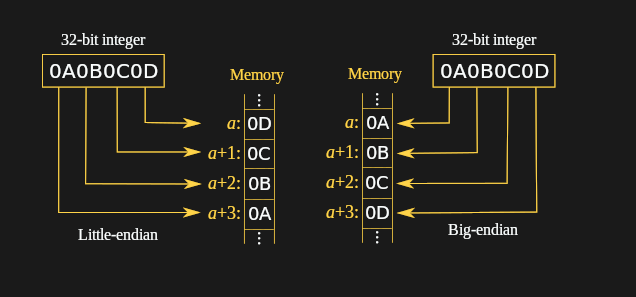
In Little-Endian (x86-64), it is stored in memory as:
| Memory Address | Byte Stored |
|---|---|
[rbx] (lowest) | 0x0D |
[rbx + 1] | 0x0C |
[rbx + 2] | 0x0B |
[rbx + 3] (highest) | 0x0A |
So, if you did a memory dump, you would see the sequence: 0D 0C 0B 0A. The mov eax, [rbx] instruction is “endian-aware”—it automatically reads these 4 bytes and reassembles them correctly into the register as 0x0A0B0C0D.
Representing Numbers: Two’s Complement
We’ve seen how bytes are ordered, but how are negative numbers represented? The standard is Two’s Complement.
To get the two’s complement of a number (to make it negative):
- Invert all the bits (change every 0 to 1 and every 1 to 0).
- Add 1 to the result.
Example: Representing -1
- Start with
1(as a 4-bit example):0001 - Invert all bits:
1110 - Add one:
1111
So, 1111 represents -1. This representation is elegant because the same CPU adder circuit can be used for both signed and unsigned arithmetic, which is why it’s universally used. All the arithmetic and logical instructions we will learn operate seamlessly on two’s complement numbers.
x86-64 Addressing Modes
Addressing modes define how the CPU calculates the address of an operand for an instruction. Addressing modes allow the programmer to access data from memory or perform operations on operands effectively. The x86 architecture supports various addressing modes, each offering different ways to reference memory or registers.
Here are some common addressing modes in x86:
1. Immediate Addressing
The data is contained directly within the instruction itself.
- Syntax: A constant numerical value.
- Use Case: Loading constants into registers or memory.
Example
mov rax, 42      ; Load the immediate value 42 into RAX
mov byte [mem], 0xAB ; Load the immediate value 0xAB into the memory location 'mem'
2. Register Addressing
The data is located in a register.
- Syntax: The name of a register.
- Use Case: Fastest data access; used for calculations and temporary storage.
Example
mov rbx, rax     ; Copy the value from RAX into RBX
add rdi, rsi     ; Add the value in RSI to the value in RDI
3. Direct (Absolute) Memory Addressing
The instruction contains the absolute memory address of the data. This is rare in 64-bit code.
- Syntax: A constant address in square brackets
[]. - Use Case: Accessing a specific, fixed memory location (like a global variable).
Example
mov rax, [0x4000] ; Load the 8-byte value from memory address 0x4000 into RAX
; In practice, you'll usually use a label:
mov rax, [my_var] ; Load the value at the address represented by the label 'my_var'
4. Direct Offset Addressing
This is one of the most powerful and common modes. It allows you to combine a base register with a constant displacement.
- Syntax:
[base_reg + constant_displacement] - Use Case: Accessing fields of a
struct(where the displacement is the field’s offset) or local variables on the stack (relative toRBP).
Example
mov rdx, [rbp - 8]   ; Load a value from the stack, 8 bytes below the address in RBP (likely a local variable)
mov [r12 + 16], rcx  ; Store RCX at the memory address 16 bytes past the address in R12
OR
byte_table db 12, 15, 16, 22  ; Table of bytes
mov al, [byte_table + 2]      ; Load the 3rd byte (16) into AL
mov al, byte_table[2]         ; Same as previous instruction
5. Register Indirect Addressing
A register contains the memory address of the data. The register acts as a pointer. The primary registers used for this are BX, BP, SI, and DI.
- Syntax: A register name inside square brackets
[reg]. - Use Case: Iterating through arrays or data structures by updating a single pointer register.
Example
mov rsi, [rdi]   ; RDI holds an address. Load the value from that address into RSI.
mov [rbx], rax   ; RAX holds a value. Store it at the memory address contained in RBX.
64-bit x86 adds 8 more general-purpose registers, named R8, R9, R10 and so on up to R15.
- R8–R15 are the new 64-bit registers.
- R8D–R15D are the lowermost 32 bits of each register.
- R8W–R15W are the lowermost 16 bits of each register.
- R8B–R15B are the lowermost 8 bits of each register.
The Stack
The stack is a crucial region of memory managed in a Last-In, First-Out (LIFO) manner, like a stack of plates. Data is pushed onto it and popped off in the reverse order.
- It’s controlled by two registers:
rsp(Stack Pointer) andrbp(Base Pointer). - The
pushinstruction decrementsrspand places a value on the stack. - The
popinstruction retrieves a value from the stack and incrementsrsp. - Uses: Storing temporary data, saving register values before a function call, passing arguments to functions, and creating local variables.
The Stack is usually used to pass arguments to functions or procedures and also to keep track of control flow when the call instruction is used. The other common use of the Stack is temporarily saving registers.
We will explore the stack in great detail in the final chapter on procedures.
Following animation will help you in getting clear picture.
Putting It All Together: The Big Picture
Let’s visualize how these components interact when a simple C program like c = a + b; is run.
- Fetch: The CPU’s control unit reads the
mov eax, [a]instruction from memory (addressed byRIP). - Decode: The control unit understands this means “load a value from memory.”
- Execute (Memory Read): The memory address of
ais calculated, and the value is fetched from RAM and placed into theeaxregister. - Fetch/Decode/Execute (Next Instruction): The next instruction,
add eax, [b], is processed. - Execute (ALU): The ALU receives the values from
eaxand from memory addressb, adds them together, and places the result back intoeax. - Execute (Memory Write): A final
mov [c], eaxinstruction writes the result fromeaxback to memory addressc.
Throughout this process, the RFLAGS register is updated. For example, if the result was zero, the “Zero Flag” would be set to 1.